Arch 655| Project 01: Galaxy SoHo
Neda
Sadeghi
Fall
2019
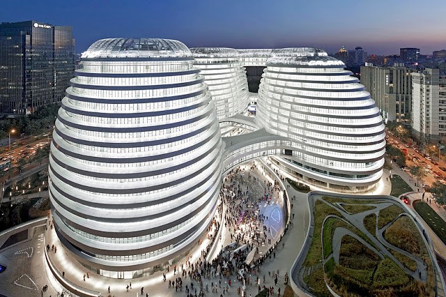 |
| Fig.01 Galaxy SoHo Facade |
· Project Basic Information
Architecture: Zaha Hadid Architects
Location: Chaoyangmen, Beijing, China
Project Type: Mixed-use commercial development
Construction Year: 2009-2012
Plot Area: 46,965 m2
Built Up: 330000 m2
Max Height: 67 m
Total Floors: 18
· Project Definition
The Galaxy SOHO project in central
Beijing for SOHO China is a 330000m2 office, retail and
entertainment complex that will become an integral part of the living city,
inspired by the grand scale of Beijing. Its architecture is a composition of
five continuous, flowing volumes that are set apart, fused or linked by
stretched bridges. These volumes adapt to each other in all directions,
generating a panoramic architecture without corners or abrupt transitions that
break the fluidity of its formal composition.
 |
| Fig.02 Top View of Galaxy SoHo |
· Project Concept
The Galaxy Soho building comprises four main
domed structures, fused together by bridges and platforms between curving floor
plates to create a fluid environment that surrounds a series of public
courtyards and a larger central "canyon".
· Facilities
The mixed-use development features 18 floors,
15 above ground and 3 below ground, with retail units around the central canyon
and courtyards on its four lower levels and office units occupying floors 4-15.
The retail units are connected by sky bridges providing access to various
levels of the building.
In addition, Galaxy SoHo’s exterior has
been designed with aluminum and stone, while the interior features glass,
terrazzo, stainless steel and glass reinforced gypsum.
 |
| Fig.03 Top Graphical View of Galaxy SoHo |
· Modeling Process
The modeling process of SoHo Galaxy is
described in this section. The model is built by applying Grasshopper Plugin in
Rhino Version 6.00 with using Parametric Tools such as Kangaroo, springs etc. The
modeling process can be divided into 5 sections as follow:
-
Modeling The Buildings
-
Creating The Shape
-
Creating the Roof for each Building
-
Creating the Bridges between Buildings
-
Linking the Buildings to each other
through Bridges
o Modeling The Building
To start, the first step is creating Ellipse
by defining the point and two Radii. To create the first base of Building.
 |
Fig.4 Creating a Ellipse with defined Radius and Assigned point as a building base
|
Then,
to creating the No. of floors, the move and Scale functions are applied to
create the No. of floors.
 |
| Fig.05 Creating Series to generate the floors of building |
o Creating the Shape
As
you see in Fig. 6, the outside shape of towers can be defined by applying Graph
Mapper and range function.
 |
| Fig.06 creating the outside shape of Building by applying Graph Mapper and Scale Functions |
In addition, we can change the outside shape of tower to desire shape by changing the Graph Mapper Function. In this project, I use the Bezier curve as Graph Mapper type. You can choose another curve types to have your own desire shape. In the following Fig.07, the modified outside shape is presented. Besides, you can change the outside shape of tower by changing the amount of ellipse’s radii.
o Creating the Roof for Each Building
To create the roof of tower, the pipe function is applied to create the roof. The location of the pipe can be defined through defining the item function. This roof is parametric variable and when the height of floor is changed the roof can be added to the last floor.
 |
| Fig.07 creating the roof by applying Pipe Function and assigning it to the last floor |
Based on the same instruction and same
functions, I create the all of four building as well.
 |
| Fig.08 Four buildings of Galaxy SoHo are modeled |
o Creating the Bridges Between Buildings
Before creating bridges
between two buildings, the first step is to define the points on our costumed
shape.By applying points on the curve functions, we create the line between
points and then the Arc between two buildings be produced.
 |
| Fig.09 to Arc between two buildings are defined based on points on the curves |
To create the bridges between the buildings I apply the sweep 1 based on the curves which are already created from the points( Fig.10)

Also, the location of bridges can be
defined based on the considered floor. I created the bridges between two
buildings in floors 4th and 14th. The challenges of this project is in this step,
which the height of bridge must be defined.
 |
| Fig.11 to assign thickness to the Bridge |
To assign the height for
the bridge, it is supposed to find the plane of bridge based on the origin
plane. You can also change the height of bridge in the Z direction.
 |
| Fig.12 the Created Bridges between Buildings |
o Linking the Buildings to Each Other Through Bridges
All of the linked bridges are created based on
the same functions and procedures.
 |
| Fig.13 Final Model of Galaxy SoHo |
§ Physically Based
Model
One
building of Galaxy SoHo is considered to create physically based model by using Kangaroo and Weaver Bird. Two
different type of anchor points are applied to analyze the physically based
Model.

 |
| Fig.15 the Geometry Output of First Model of Kangaroo Analysis |
 |
| Fig.16 the Geometry Output of Second Model of Kangaroo Analysis |
§Analyzing the Curved Surfaces in Terms of Geometry Using Color-Mapping
 |
| Fig.17 Analyzing the Curved Surfaces as a Geometry by Applying Color-Mapping/Gradient |
 |
| Fig.18 Final Render Model of Galaxy SoHo |
 |
| Fig.19 Zebra Analysis of Model on Horizontal Direction |
§Perspective View
of Model in Photoshop
 |
| Fig.20 Final Model of Galaxy SoHo |
References

Comments
Post a Comment